6 pin cdi wiring harness
1 2 3 4 5 6 7 8 9 Share No views 12 minutes ago Looking to wire up your motorcycle CDI? In this video, we walk through a basic 5 pin CDI wiring diagram.

Kitaco Cdi Wiring Diagram diagram wiring vespa
The first step to wiring a 5-pin DC CDI is to identify the components you'll need to make the connection. This includes the power source, ground, and the five pins on the CDI. Once these components are identified, you'll need to create a wiring diagram to show the correct wiring connections. When drawing the diagram, it's important to.
wiring diagram for 49cc quad
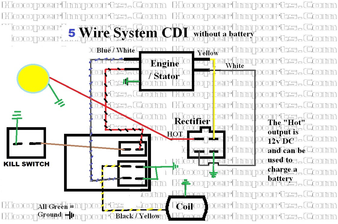
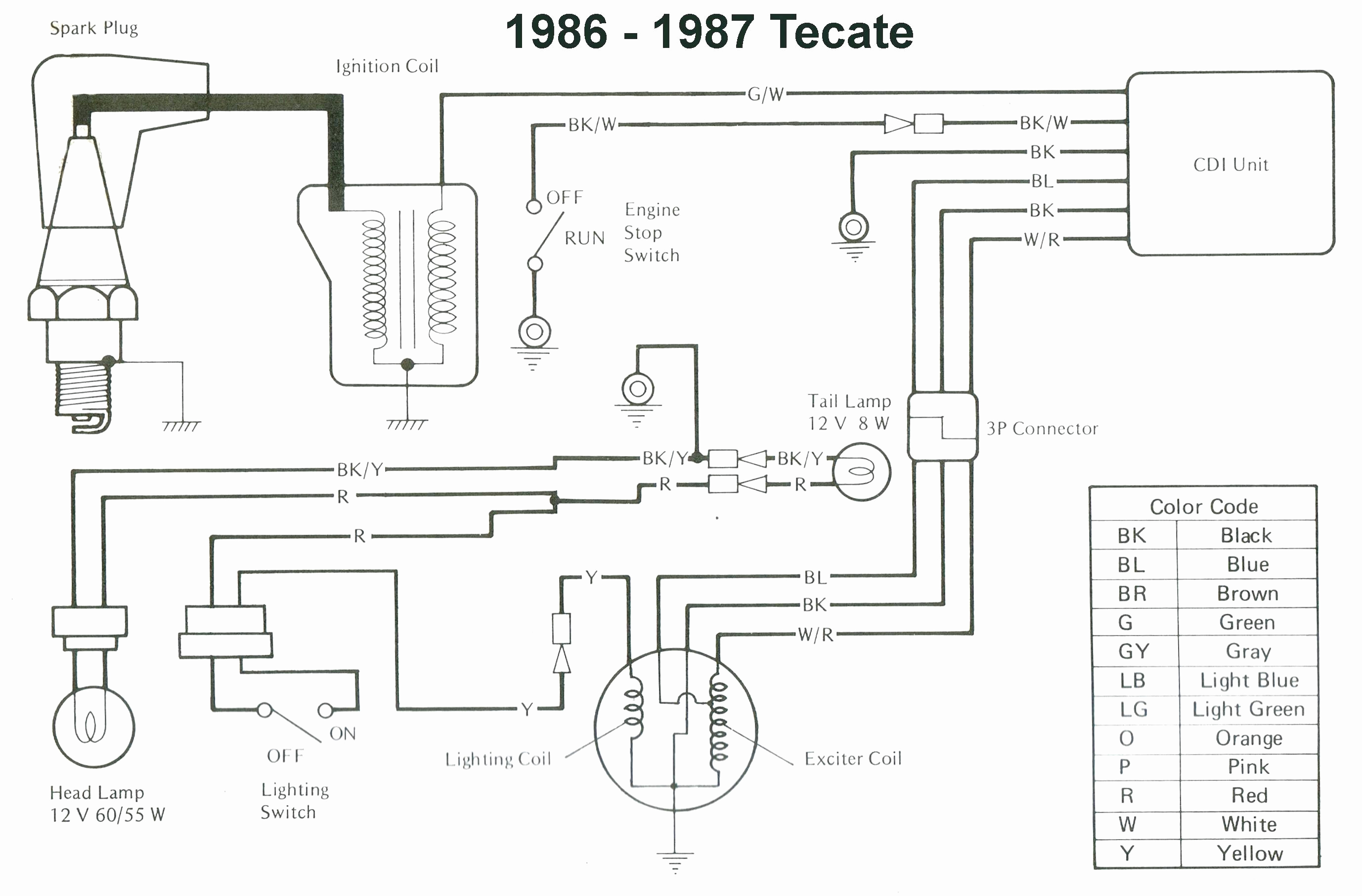
VI. 5 Pin CDI Wiring Diagram - AC CDI Box or DC CDI Box? - AC CDI Box - DC CDI Box VII. Conclusion What Is A CDI System? The Capacitor Discharge Ignition (CDI) is an electronic ignition device used in many motorcycles, scooters, ATVs, UTVs, Go-Karts, lawnmowers, and outboard motors. It is the most important part of the ignition system.

5 Pin CDI Wiring Diagram (Pictured AND Explained!) OffRoad Official
The Complete Guide to 6 Pin CDI Wiring Diagrams Team AutomadeSimply Updated onSeptember 4, 2023 If you own a motorbike, ATV, or other small engine vehicle with a CDI (Capacitor Discharge Ignition) system, you've likely needed to diagnose an ignition problem at some point.

5 Pin Cdi Wiring Diagram Wiring Harness Diagram
The 5 Pin Cdi Diagram: A Simple Guide to Understanding Its FunctionThe world of motorcycles can seem complex and intimidating, especially for beginners. With so many different parts and components, it can be overwhelming to try and understand how each one works.. Yamaha Qt50 Ing Cdi Box Jog 5 Wire Questions Moped Army. Service Manuals The.
5 Pin Cdi Wire Diagram Manual EBooks 5 Pin Cdi Wiring Diagram
The 5 pin CDI wiring diagram is a crucial tool for automotive repair professionals. It provides vital information about the internal workings of a car's electronic ignition system. This diagram is typically used to troubleshoot issues with a vehicle's engine performance, such as a shorted spark plug wire.
5 Pin Cdi Wiring Diagram Wiring Diagram
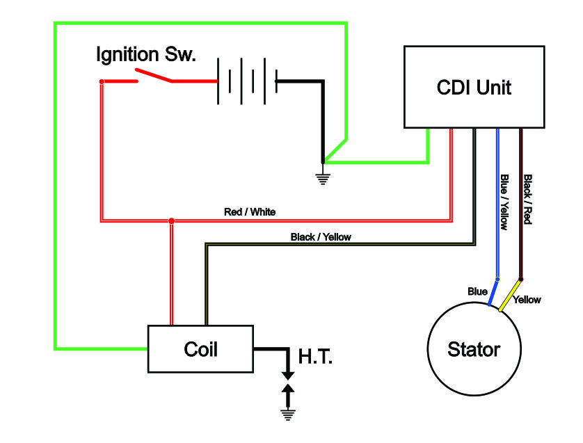
A 110cc 5 Pin CDI wiring diagram contains several components that work together to create the circuit. Each of these components plays an important role in the functionality of the system. Let's take a closer look at each element: CDI Unit: This is the central control unit for the entire system.

Chinese 5 Pin CDI Wiring Diagram (Pictured & Explained) OffRoad Official
In this complete guide, we will break down the wiring diagram of a Chinese 5 Pin CDI, explaining each pin's purpose and how they should be connected to the appropriate components. We will also provide step-by-step instructions on how to properly wire the CDI, ensuring a reliable and efficient electrical system..
10 pin cdi wiring diagram
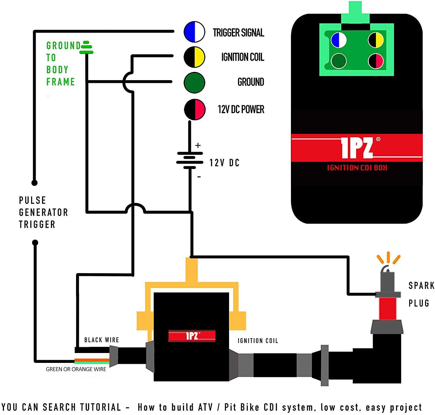
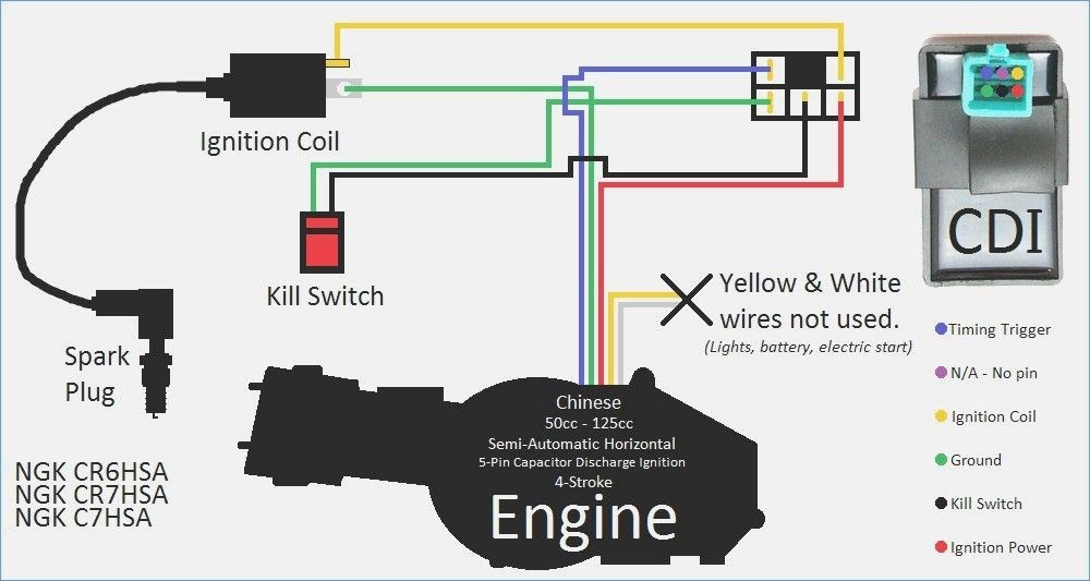
Now, let's walk through the wiring diagram for a 5 pin CDI: Pin Number Wire Color Connection; 1: Black/White: Ground: 2: Blue: Ignition Coil: 3: Red: Power Input: 4: Green: Kill Switch: 5: Yellow: Stator: It's crucial to ensure that each wire is connected to the appropriate component as indicated in the diagram. Failure to do so may result.
Chinese 5 Pin Cdi Wiring Diagram
Table Of Contents I. CDI System II. How The CDI Works III. 6 Pin CDI Box IV. AC CDI Box or DC CDI Box - 6 Pin AC CDI Box - 6 Pin DC CDI Box V. Connecting The CDI Box - CDI Ignition Power - Ignition Coil - Timing Trigger - Kill Switch Or Ignition Key Switch - Ground Wires VI. 6 Pin AC CDI Wiring Diagram VII. 6 Pin DC CDI Wiring Diagram VIII.
5 Pin Cdi Wiring Diagram Cadician's Blog
Ground Connecting Chinese 5 Pin CDI Box When purchasing a new CDI Box, many times you can purchase a kit that also includes a new wiring harness along with it. But the Chinese 5 pin CDI box should attach to the stock wiring harness in your vehicle as well.

4 Pin Cdi Box Wiring Diagram
A 5 pin CDI diagram is a schematic representation of the 5 pins used to hook up the different components of an engine's Electrical Control Unit (ECU). The diagram typically shows the wiring for the ignition system, which includes the ignition coil, spark plugs, and distributor.
Atv Cdi Box Wiring
The five pins connect to the following components to provide power to the engine: Timing trigger (or pulse generator) Ignition coil CDI ignition power
5 Pin Cdi Wiring Diagram Cadician's Blog
A 5 pin CDI wiring diagram is a diagram that shows the wiring layout for a specific type of 5 pin CDI (capacitor discharge ignition). This type of diagram is used by automotive and motorcycle mechanics, as well as other vehicle enthusiasts, to identify and troubleshoot issues with their vehicles. A 5 pin CDI wiring diagram will usually show the.
Bestly Gy6 Ac Cdi Wiring Diagram
1 - timing input - Blue wire. 2 - empty. 3 - is power out to the HT ignition coil - Yellow wire. 4 - ground - Green wire. 5 - kill switch (grounds to kill engine) - Black wire. 6 - power input from the stator - Red Wire. Or if you're just running it off the wires: yellow (from the CDI box) - Out to HT coil. blue from box - Timing impulse in.

5 Pin Cdi Wiring Diagram Color Code
The 5 pin CDI diagram includes five pins that are connected to the electronic control unit (ECU) of the vehicle. These pins will connect to the battery, ignition coil, and spark plug. The diagram also shows the wire connections between the ECU, ignition coil, and spark plug. The battery is the first connection point in the 5 pin CDI diagram.