
Wiring Diagram To Maglock Iei Keypad Iei 212 Keypad Wiring Diagram Wiring Diagram It shows
When power to the magnetic lock is turned off, the electromagnet releases the armature plate, allowing the door to open. SPECIFICATIONS 80-LB. MINIATURE ELECTROMAGNETIC LOCKS 12~24VDC 23/ 4 x 11/4 x 13. FIG. 3 Wiring diagram 12345 Steel and Rubber washers (as needed) Steel and Rubber washers (as needed) Power wires to electromagnet Control.

Wiring Diagram To Maglock Iei Keypad Wiring Diagram Schemas
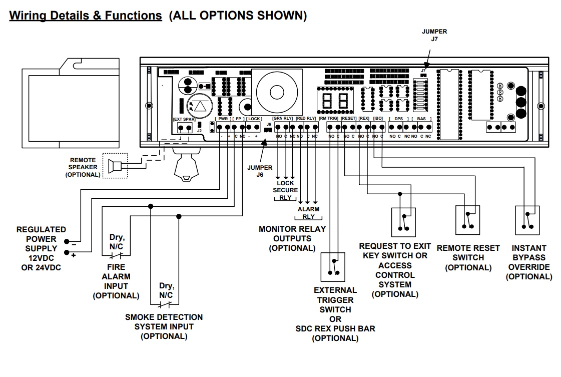
MAGNETIC LOCK WIRING INSTRUCTIONS MODELS WITH BOND SENSOR AND DOOR STATUS SENSOR 600LB, 600DLB, 1200LB, 1200D To remove the header plate, it may be necessary to remove the wiring compartment screw. A long wiring compartment screw can be used to increase security by limiting access to the header plate mounting

Wiring Diagram For Door Lock
1. NOTE TYPE OF DOOR FRAME HEADER AND INSTALL FILLER PLATE OR ANGLE BRACKET AS REQUIRED TO PROVIDE A FLAT MOUNTING SURFACE ON THE DOOR HEADER THE ENTIRE LENGTH OF THE MAGNETIC LOCK. OUTSWINGING DOOR INSTALLATION HEADER OUT SWINGING DOOR HEADER PLATE MAGNET ARMATURE PLATE HEADER OUT SWINGING DOOR FILLER PLATE MAGNET ARMATURE PLATE HEADER OUT

Maglock Wiring Diagram Free Wiring Diagram
Mini Integrated Delayed Egress Magnetic Locks . Datasheet. DE Code Compliance . Installation . 1581S purchased after 07/2019 . 1581S purchased before 07/2019 . Annunciators . 700RU . 728RU .. Sample Wire Diagrams ) Push Plates & Panels . 480 Push Plates, Actuators & Touch Panels . Datasheet. Installation . 480A1U / 480O1U . 480A2U / 480O2U.
Wiring Diagram For Maglock
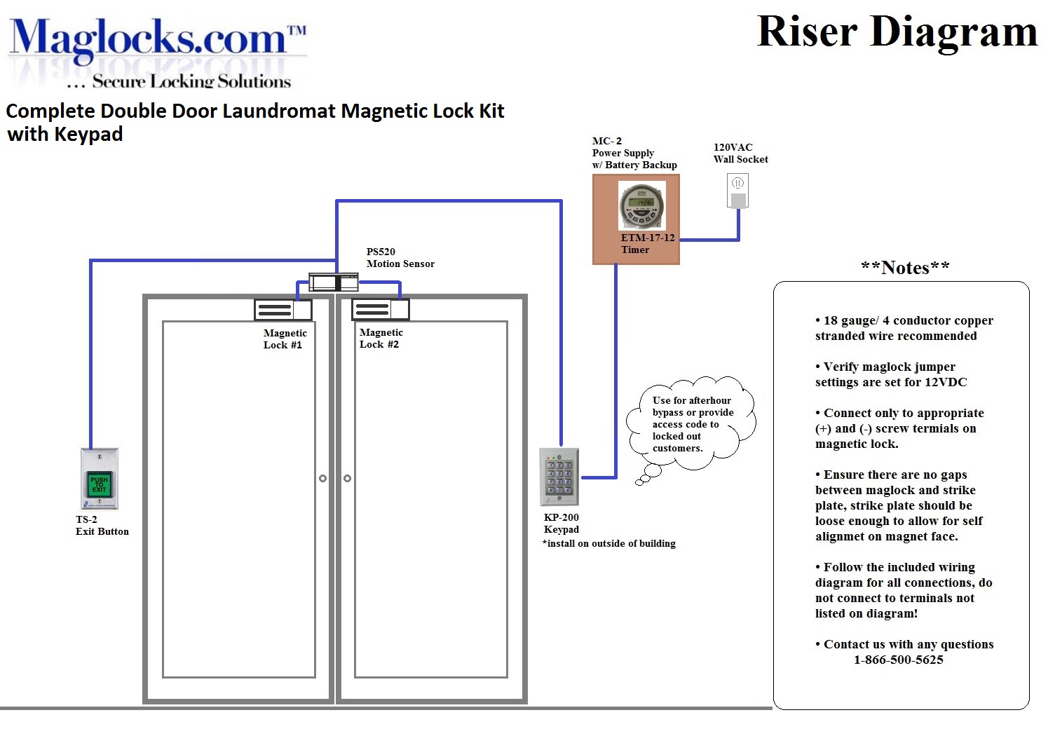
Magnetic Lock Wiring Diagram. Much like the door access control system diagram above, the mag lock wiring diagram relies on a few simple basics: electricity supply, switches, and, of course, locks. Magnetic locks, also referred to as mag locks or maglocks for short, rely on a constant flow of electricity to stay sealed. When that power is cut.
Wiring Diagram For Maglock
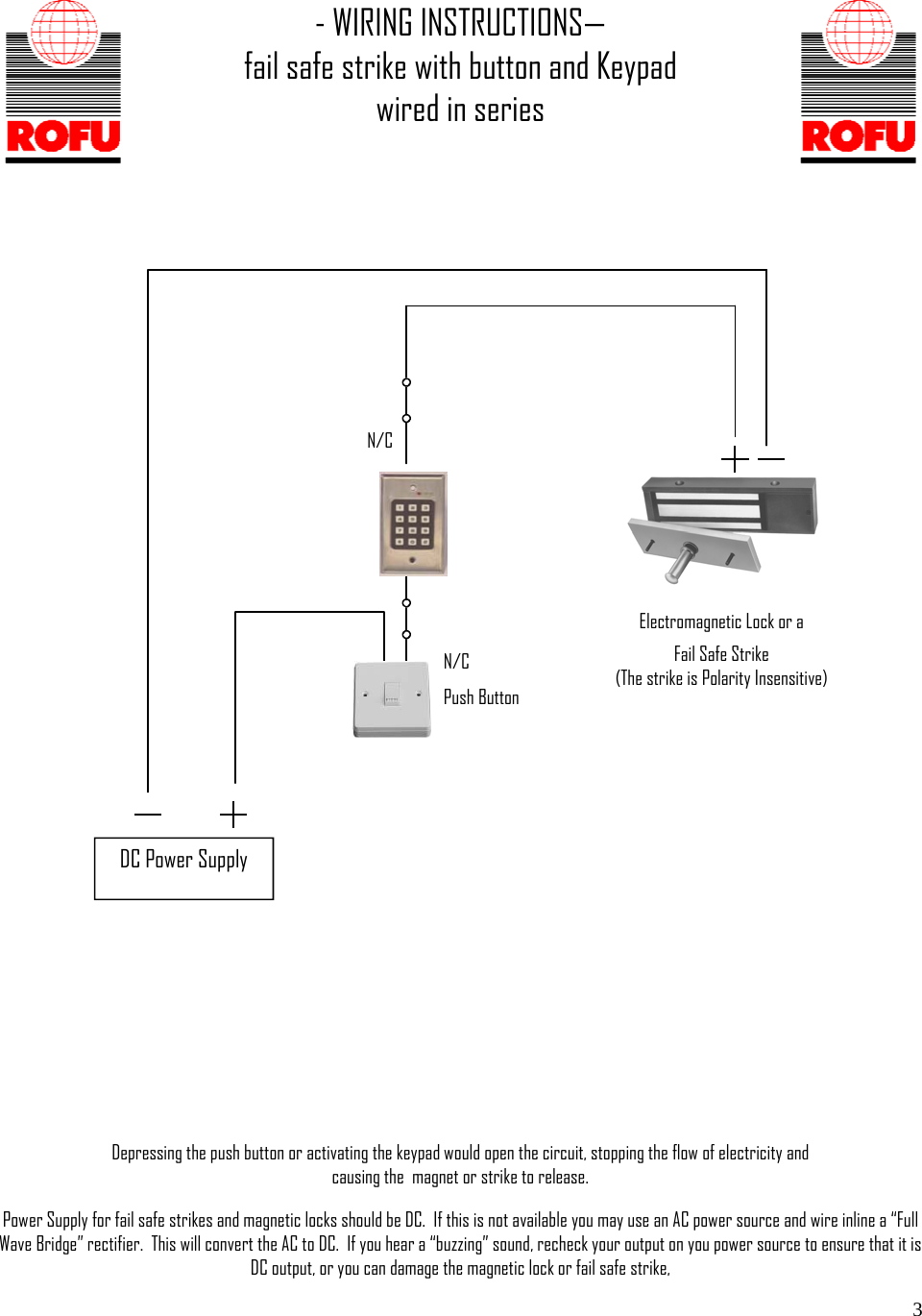
Standard wiring diagram for a bolt or Electric Strike Helpful? Mag Locks Using Mag Lock Standalone with mushroom button Related articles NEO ACR - Connect 2 ACR with one locking system (electric strike or mag lock) Lock-S Lift Control Mag Lock Wiring Diagram Standard wiring diagram for a bolt or Electric Strike
Mag lock
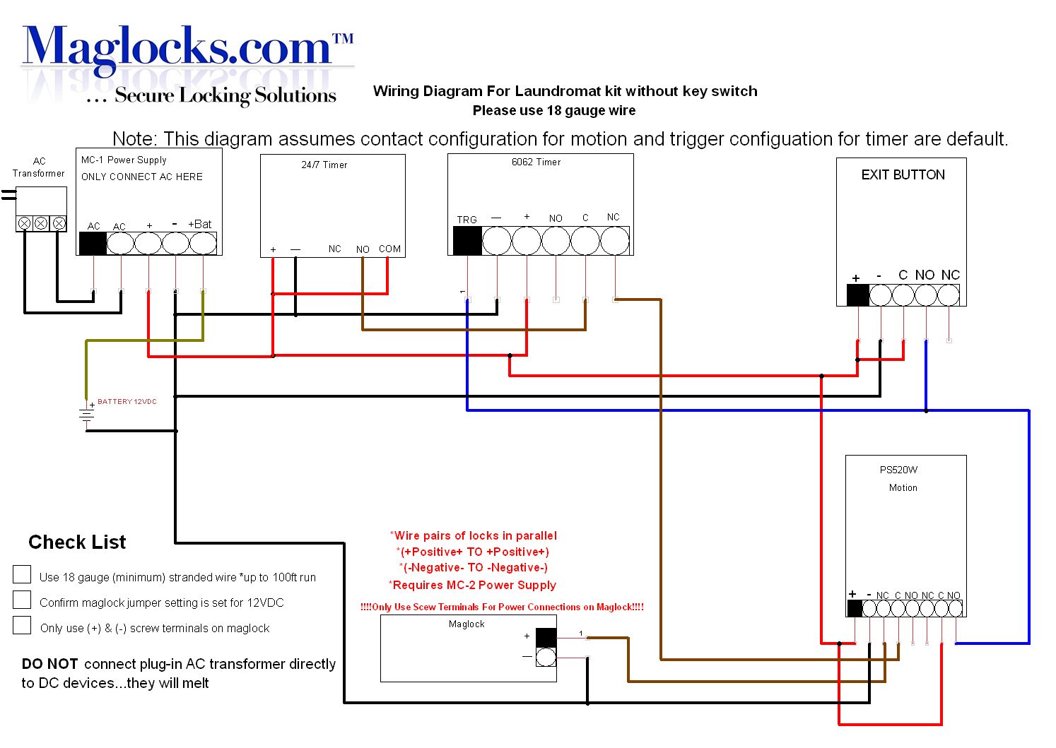
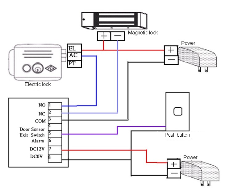
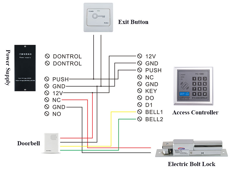
Connect the positive wire of the maglock (For TOPLOCK magnetic door lock, it's red) to the "+12V" pole of the power supply. Link the negative wire (For TOPLOCK maglock, it's black) to the "GDN" pole. The electric circuit loop is formed. The magnetic door lock can perform normally by connecting and disconnecting the wires to the.
Mag lock wiring diagram for SCS300k
How to wire a magnetic lock with, backup battery, exit button and key switch. This and other diagram and tutorials are available on our website at; www.therealfileguru.simplesite.com.

PI Manufacture
You can purchase our magnetic lock kits at https://allsecurityequipment.com/collections/magnetic-locks-magnetic-lock-kitsInstructions on how to wire a magnet.
External Mag Lock Wiring Diagram Wiring Diagram Schemas
The electromagnetic lock (EM lock) is also known as magnetic lock, or maglock. We will learn how electromagnetic lock works, how to connect electromagnetic lock to Arduino, how to program Arduino step by step. The detail instruction, code, wiring diagram, video tutorial, line-by-line code explanation are provided to help you quickly get started with Arduino.
Wiring Diagram For Maglock
This video provides the detailed instructions with wiring diagram for the installation of a custom gate magnetic lock system including a complete battery bac.
wiring diagram for maglock
The following common wiring diagrams are available: One Single Door with Panic Bar Electric Latch Retraction, with Auto Operator; Delayed egress - Fire Rated Application;. Online Wireless WRI400 with M400 Mag Lock; Standalone Electronic Lock; Standalone with access control and Magnetic Lock; Wireless Multi-Technology Reader - GCK400;
lock wiring diagram
1. Mount the electromagnetic lock to the door frame as outlined on the installation template included with the product. NOTE: During installation of the armature plate to the door it is essential that the armature plate remains movable.
Mag Lock Wiring Diagram Images and Photos finder
Intro Magnetic Lock Kit Wiring Instructions Fast Access Security 1.99K subscribers Subscribe Subscribed 492K views 9 years ago You can purchase our magnetic lock kits at.
External Mag Lock Wiring Diagram / Single Outdoor Maglock Kit For Inswing Gates Mallory super
Magnetic locks, or maglocks, are comprised of two main parts, a mounting mechanism, and some wires. The two parts are installed on the frame and the door, so that their magnetic sides are facing each other. The mounting plate can be installed in case your door frame or door doesn't allow direct mounting.
Electric Lock Wiring Diagram gewinnspielcisa
Lock 2. The AXIS A1001 lock output connects to the separate auxiliary relay power input. 12/24 volts DC+ from a separate door power supply connects to the C terminal of the slave relay. This transfers to the NO terminal, pushing power to the lock. magnetic locks and external power supply.